Thursday 28 March 2013

Stage 2 Commences!

Broadly speaking, stage 2 has begun! After waiting almost 2 months after collecting my kit, the bolt pack and rivet/adhesive pack arrived.
So as I've been contemplating ever since ordering the kit, where do I start? How do I move forward? So many questions and no clear cut route. One thing I did find helpful was Richard's build blog: http://richards-gbs-zero.blogspot.co.uk/ This has everything! A build sequence, torques, parts, tools etc. Top blog I've seen. Anyway, having speaking to a few people and GBS, there is no specific sequence of events, just advisory notes that can help speed things up.

The Plan

This is the start of rough order/list I decided on from various sources:

1. Differential - Apparently much easier without anything in the way
2. Seat back panel
3. Footwell panels
4. Side Panels
5. Propshaft
6. Master Cylinder, Handbrake & Brake Lines
7. Fuel Lines
8. Chassis Electrical Harness
9. Drivers side transmission tunnel panels
10. Drive Shafts
11.Wishbones, hub carriers and suspension.
12. Brake discs, Calipers 13. Clutch resevoir
13. Pedal assembly & Box panels
14. Steering Column & Rack
15. Wheels

And thats about as far as I thought really. Aim is to produce a rolling chassis, obviously a few things may be missing but we'll look past that for now.

My actual sequence so far:

1. Seat back panel

 Peeled away the strips to drill and rivet. This makes removing the film much easier. After riveting I decided to just remove the whole film as this would get covered by the seats so easier to remove now.

2. Rear drivers side wishbones and hub/suspension

You'll have to ignore the panel, I've found that pictures come last as I keep getting carried away before my phone comes out for pictures.

Major point! The rear hubs from the MX5 is swapped - Left is right and right is left. This will potentially cause some problems with the brake callipers and handbrake in the future but I am told by GBS that this shouldn't be a problem.....time will tell. 

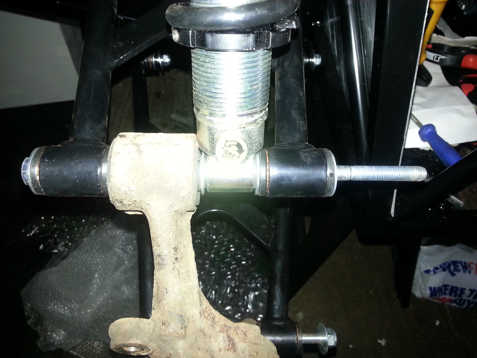
One little problem, the supplied bolt for the upper wishbone is about 10-15mm too long on the shank (see right hand picture above), meaning either it's going to get packed out with washers/a spacer or I get a shorter bolt.

3. Master Cylinder & Clutch reservoir

A quick and easy fit of the brake master cylinder and clutch reservoirs. There may be a problem with the fitting of pipework due to proximity of the outlets but some fancy pipework should solve that issue.


4. Pedal assembly

Here you can also see the pedals are currently in. Plenty of copper slip and a bit of brute force to get the brake pedal, clutch and spacer into place. These will hopefully loosen up over time as they are all very snug currently. Accelerator pedal has been swapped from this picture. I decided there was enough space on the opposite side of the bracket (nut-side as shown) that gives that extra bit of space in the footwell. Don't want to be catching 2 pedals accidentally! Also allows a bit of extra space for the push-rod into the master cylinder.


5. Footwell Panels

These were put in after the pedals as I found that when trying to get the pedals sorted, I would have knackered this panel. May need a few tweaks due to panel gaps at the bottom but it will serve it's purpose for now.


6. Rear Passenger side wishbones & hub/suspension

Got held up on this due to GBS either not updating their bolt kit from the Sierra pack or with the new upper rear wishbone design. Eitherway I was missing 4 crush tubes so I couldn't get this done with the other side. I am now realising the garage space will soon become cramped when the car gets closer to being finished....but I've seen them built in less space so it'll be fine, I'm still young and bendy.
Again I've got the same problem on the top wishbone (I tried the bottom one but this didn't solve the problem so I kept them the same to avoid confusion later.


7. Side Panels

The side panels were something I wanted to keep until nearing the end to avoid damaging them, however I need to put the front wishbones through along with the steering rack so to save taking them on and off again I just bit the bullet and will try to be more careful with the car now.


It's starting to take a bit more shape now and resemble a car now. Once the front wishbones are on and some brakes/wheels, we should be well on our way!


8. ...... - Well thats as far as I've got so far.

 
The reason for this muddled up order, following offering up the differential, I found that adaptions need to be made further to chopping the wings off. Also the steering rack doesn't fit, initial thoughts led me to believe it was because of power steering, but its not.

A trip upto the GBS factory and a Q&A session with Richard led me to find that the differential needs grinding down to flaten out to help mount into the chassis, the steering rack is in fact off a Mk2 Escort, and the propshaft and driveshafts also need adapting to ensure proper fitment. Other things included engine mounts (I reckon I can re-use the brakets off the MX5 but need to measure and check)
Update in between writing this post ~ The MX5 engine mounts are spread between 15"-17", The Zero's are 17"-19". This could end up being tight however an extension plate may help solve the issue. Would be easy and simple to knock together.

Saturday 9 March 2013

One Giant Leap

Today I managed something that I thought would be a huge struggle, however with a helping hand from Adam, a mate from uni, we managed to remove the engine and gearbox (as one) in only a few hours. With neither of us having any experience whatsoever, doing this was a case of looking around and disconnecting everything we could find. We took our time to make sure nothing was missed which would result in breakages, as I said, the key is not to rush.

The starting point was fairly straight forward as there were a few things already removed, most importantly, the radiator which I'd done a previous day. So, with no specific order, we went about removing all the electrical connections and various piping to allow the engine to come out easily.

 Once everything was disconnected, and the crane was taking the strain, the two engine mounts were undone from behind. 1 nut each side was much easier to bring the mounts out too (will probably help very nicely when loading into the kit car). Plus, these bolts behind the wishbones were easier to get at that the 4/5 on the mounts to the engine. One part we missed on removal was the gearstick. It was only when we tried pulling it forward we realised something was catching. Removing the 3 screws and the stick and blanking off the hole with tape, we were back on our way.

 Here we are starting to tilt the engine back with a bit of man-handling to ensure the gearbox comes up without getting damaged on the transmission tunnel. Another set of connections we found were behind the engine block which only came apparent as we could get a better look as it moved out. Same occured with the gearbox which had a few electrical connections and a P-clip holding on the conduit running down the transmission tunnel.
 From this picture to the right, you can see the exhaust manifold is still attached. I aimed to remove this prior to removing the engine however with the limited space, it was left on. This later changed as we lifted the engine further and further out to a stage where I could get a spanner in and remove the braket from the gearbox and get the branch, collector and down pipe off in one go, freeing up a little bit more space for the assembly to be removed.

 
 Here we are, the final straight, finish in sight. The whole assembly out and on the final stages of the removal.

Looking like it's precariously balanced, but is actually clear and being held on the seat belts and crane.

 Success!!! The engine is out and the car now looks much more empty. Well duh, it is empty!


 Resting on the floor, I managed to clear enough space to pull it back.

Seemed like the right thing to do, I can now say I am the powerhouse of an MX5. Already the sense of achievement is building. Who'd have thought back in October when this idea came to me, that I would be stood in the engine bay of the MX5? I must say, I am very surprised myself to have got this far and it really gives me confidence that I have not bitten off more than I can chew. Looking forward to finishing the project now.


 We could have called it a day there and then but the steering rack and column was now accessible and hoepfully would be an easy job. Turns out, I think I may actually have power steering (something which eluded me whilst driving, obviously faulty). Nevertheless, we cracked on, removing the supporting bracket of the column at the back of the footwell and dashboard bracket, removed the rack supports and then the joint to which they were attached. One of the bolts needed cutting out which gave me the perfect opportunity to use my newly exchanged angle grinder. As sparks flew over the various fluid covered floor and Adam on fire extinguisher standby, it came through with no drama at all.
small large tug from both ends and the rack and column it came undone and is now sat in half.


The last task of the day was to re-fit the camcover to help protect the insides of the engine. If I don't say so myself, a very nice looking finish. Maybe the intake manifold will be the same one day...

Anyway, going home happy tonight, this is a giant leap forward.

Sunday 3 March 2013

A few minor adaptions

A quick check and the diff does need an adaption. As seen in a previous post, the diff has to be adapted to make it fit into the new chassis. The main thing is the "wings" with which it helped mount under the car need to come off, easy job really, a quick trip to Screwfix for a 9" angle grinder and some cutting discs and jobs a good'un, Made quick work of it and not bad for my first ever experience of doing anything like this. In the dark with a torch round the back of the house using my foot to steady the object....what could possibly go wrong?! Well, I'm still walking on both legs and there aren't any chunks missing from the surrounding area so all good.

Anyway, here is the finished product:


Saturday 2 March 2013

Making Progress

 Now we are making progress! Finally got the diff out with a bit of force and strange techniques it eventually came out. The problem I found, it that the brace/strengthening beam attaches all the way down the the gear box and has wire clips plugged in all along it. However the bolts came out no problem and a chisel made short work of the clips. However, the beam is still attached using witchcraft or some hiding bolts. Eitherway will have to work that off before putting it into the new chassis.
 The propshaft and other final drive shaft now out as well, thought it would be a good idea to glove the gearbox spline end of the propshaft to prevent dust and dirt contamination.

 
<- A view of the gearbox from underneath the car.

And one of where the differential used to sit ->


One of the problem front hubs. I've been told these are easy to remove however I am starting to find them a little more difficult due to rust and fatigue of parts over their 23 year life.
Speaking of rust...
This is a photo of the front part of the diff, with either chunks of metal or just a build up of rust pulling off in flakes. Will need a tidy up but no need for painting as that will be too much hassle.


 These two picture show the beam that is currently stuck on as I said before. It appears to have a connection somewhere that is allowing the beam to pivort, however hammering didn't solve the problem, maybe a look at a detached diff will enlightem me further which section to hammer...