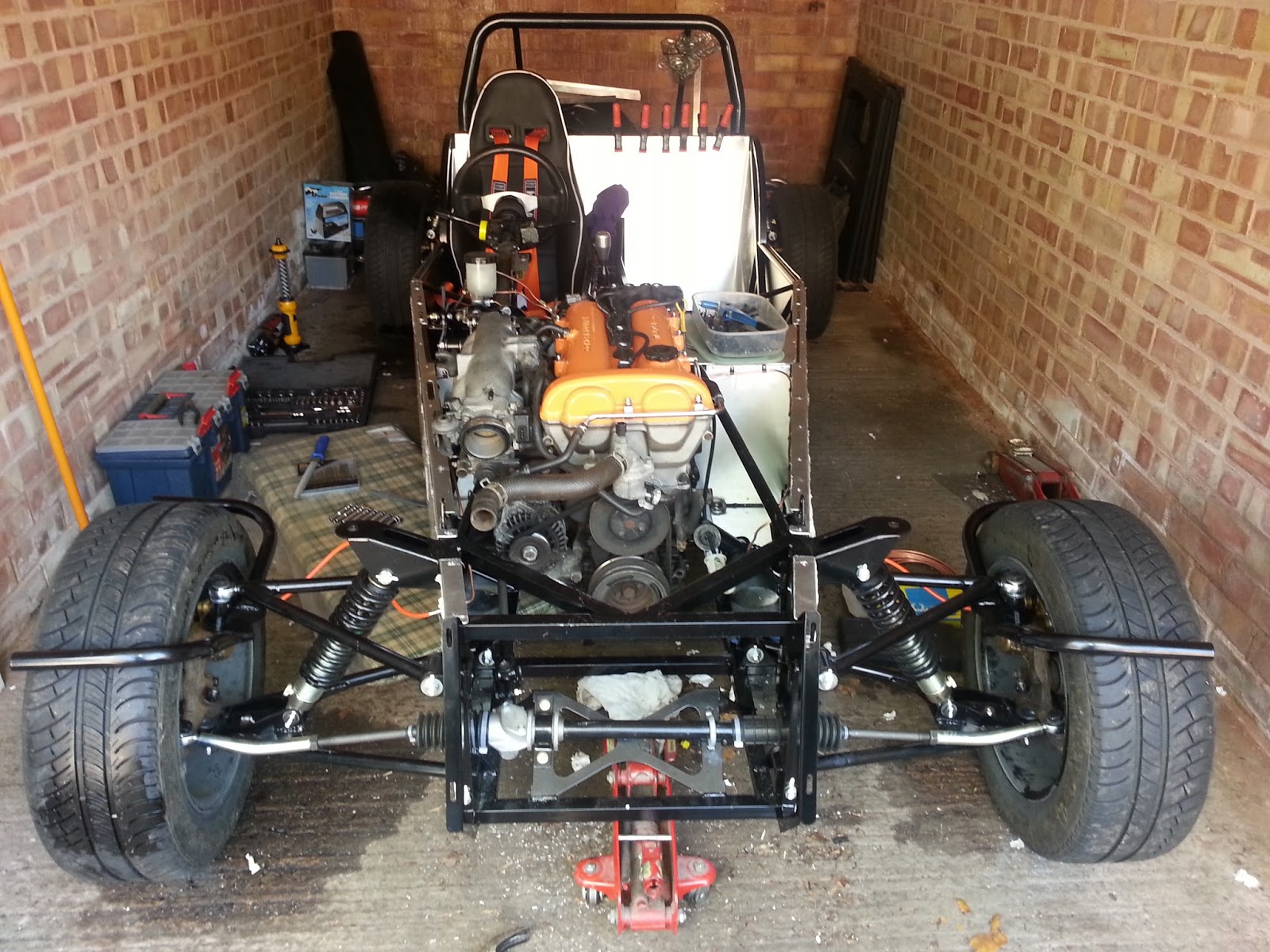
Massive milestone today! We have touch down!


As you can see here, the chassis is now rolling and the real size of the car is coming to light. Big thanks to Adam (Mate from Uni) for helping out and also to Dan (brumster - RHOCaR) for lending me the engine crane to do so!
Below are a selection of photos telling you of the story of how the above photos were achieved. It started off with lifting the chassis at the centre point of the transmission tunnel where the frame begins to expand under the dashboard. 50-50 weight balance supposedly.... yeah right! Squeaky bum time as the car was lifted off the stands and made a break for the wall!


In the end, it was down safely. As the steering wasn't connected and I am still waiting on a handbrake from GBS, I made the toe quite extreme to avoid any unwanted getaways.

With the frame on the floor, it was only natural to sit in the car as seen above.....and so much fun! Just a taster of what is to come I hear.
Anyway, after manoeuvring the engine crane back out of the garage, the next step was the engine. Luckily I had been able to strip the MX5 in a garage in Cannock and build the Zero in Tamworth. Which was great until I had to transport the engine in the back of a van. Nearly as nervy as the time I picked up the kit! Every bang and crash brings that extra little bit of panic...but it all was ok and in it goes - as one with the gearbox, easier that fiddling about with bolting them back together.


Some slight adjustments on the mounting points. These for the Mazda fit one way and one way only. They ARE different and will only fit on the 4 holes they were designed to. We had tried to fit the mounts on the block and then lower the engine in, however with a number of clashes (air intake and alternator), a single mount was removed and whilst one was located, then the other one was fitted and pulled the engine square. So simply, fit the hardest to reach mount, then fit in the easier side as the engine is getting close.

Fitting the gearbox was interesting. We had swapped the mount around a number of times (reason will come later) which cause a lot of trouble...especially when we had it right first time! Anyway, the engine was now in and looked to be all ok and in the right position.......
 Even the steering shaft was looking tight but is ok....
So what's the problem I hear you say.....................???
Well....
 The propshaft wasn't fully connected. It was originally thought we had the gearbox mount the wrong way round, that would give us the distance needed...but the engine mounts were already at the right point...so it was swapped again...then out again to tidy up the location slot and increase the length of it just a bit thinking that was the problem...back on and still no (it helped with the engine mounts to be fair) so what on earth could it be?
It would appear that the propshaft supplied by GBS is actually too short but that couldn't be right......A double check of the mounts, some measurements and head scratching and a quick tea break and still no solution. I was really starting to doubt myself now.
A quick mental checklist was done:
- Engine mounts were located in the correct place
- Gearbox mount (despite numerous changes) look right
- The engine appears to be generally in the right place from memory of other Zeros
- The gear stick is in a comfortable place
- The engine can't actually move back any further (or far enough) due to it begin to clash with the chassis.
So with all this in mind, a call to GBS was made. Richard, also scratching his head, dug out his measurement notes: Diff prop flange to gearbox oil seal = 640mm
Mine = 680mm. Ah well there is the problem!
I must have something wrong....but as said above, I can't see anything out of place. Richard also agrees from the pictures sent. Possibility of the diff being a different flange plate due to limited slip? Quite likely...Richard is on the case! Update! Richard has got back to me and established that the nose of the limited slip diff (that I use) is 40-50mm shorter than the one GBS have used. New propshaft is required.
Anyway, undeterred, the steering was linked up and the wing bracket bolts tightened up now they are on the floor and running closer to their proper height


Anyway, all in all, a very successful weekend! The car is now clearly a car and a major milestone has been achieved. Next step is the electrics. Aim is to get the engine ready to run and lights all working. This will be the frustrating and long process. Can't say I'm looking forward to it as I really am going in blind, but the end goal will keep me calm and focused. I now have a place to sit and think (and pretend to drive) when things are needing a break. Overall, I am a very happy chappy! Just getting to this stage is worth all the cuts and bruises and scuffs and bangs and pain...the list goes on.


